


How Does an AC Axial Cooling Fan Maintain High CFM Under Dense Dust Filter Resistance?

A control cabinet in a dusty plant often has a thick dust guard. The pad catches particles well. But it also chokes the airflow of a normal axial fan. Free-air ratings mean little once that pad gets loaded, and cabinet temperatures go up.
Three things keep CFM up under this load: motor torque reserve, pressure-focused blade design, and system-level optimization. A well-matched ac axial fan keeps its speed and airflow as resistance rises. A high static pressure axial cooling fan pushes through the pad instead of stalling against it.
This post also shows where a high-static-pressure axial fan fits best. It also shows where a compact forward-curved centrifugal or plug fan works better for very high static pressure. Both are good choices.
Key Takeaways
A powerful motor keeps the fan spinning fast, even when a dust filter blocks the airflow.
Special blade shapes push air through resistance without losing power.
A well-built cabinet and changing the filter often lower resistance and keep airflow steady.
Pick a centrifugal fan only when the resistance is very high.
Always check the real airflow when the filter is at its dirtiest, not just the number in the catalog.
Static Pressure and Filter Resistance
The Fan Performance Curve
A fan's catalog rating tells only part of the story. Manufacturers measure rated cfm at zero resistance, with free air moving through an open inlet. The same fan reaches its maximum static pressure at shutoff, where the impeller spins but no air passes through. Between these two extremes sits the fan p-q performance curve, and every real installation lands somewhere along it.
A dense dust filter adds resistance to the cabinet's air path. That resistance rises with the square of airflow, so the system resistance curve climbs steeply as more air tries to pass. Where this curve crosses the fan curve, the two balance. That crossing is the operating point on the fan curve, and it sets the actual airflow delivered. A fine-mesh dust filter on a dusty plant cabinet pushes that crossing far up the curve. Fan airflow drops, and the cabinet runs hot.
Free-Air CFM vs. Filtered CFM
Free-air numbers make an axial fan look better than it is. Once a filter pad loads with dust, the fan curve behavior changes the result. The gap between rated cfm and real airflow grows as back-pressure rises. Buyers who size on catalog figures often find installed airflow far below the plan.
Air density changes delivered airflow too. Higher altitude and hotter air thin the airstream, and each round of dust loading adds resistance. The fan curve stays fixed, but the operating point slides. Designers should read the fan curve at the filter's clean and dirty limits, not at free air. That habit protects real airflow through the whole service interval.
How an AC Axial Fan Holds Speed
Torque Reserve Under Load
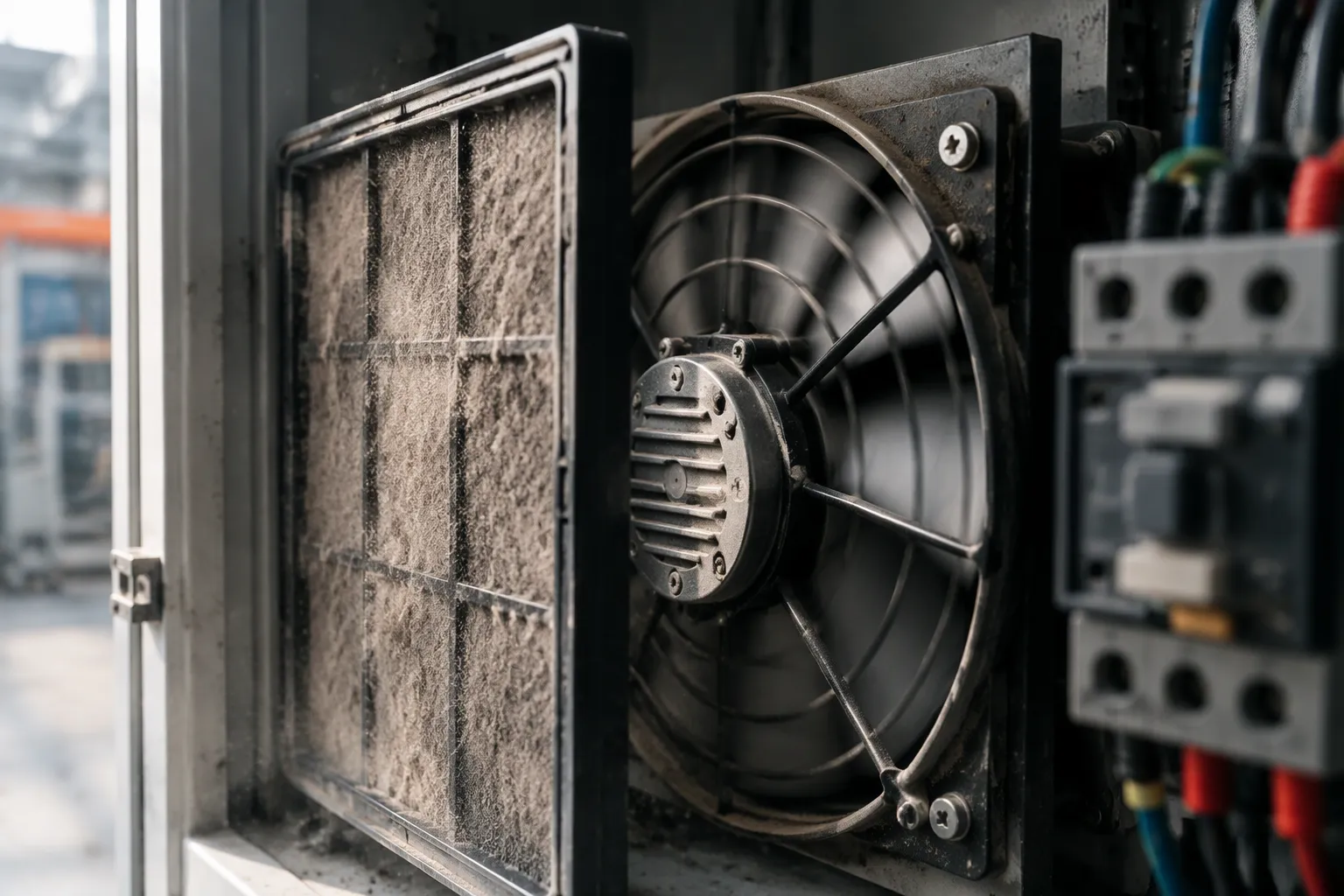
An AC induction motor spins a fan impeller at a speed set by supply frequency and pole count. That speed is not perfectly fixed. As load rises, the rotor slips a little behind the rotating field. A motor with plenty of torque reserve keeps that slip small. So the impeller stays close to its design speed even when a dense dust filter adds resistance. The fan curve under load then stays near its published shape, and the fan operating point barely moves.
A motor sized too tightly acts in a different way. Slip grows as static pressure climbs, speed falls, and the fan curve drops off. Delivered airflow falls faster than the filter alone would cause. This matters in dusty plants, where a cement or mining control cabinet may run for months between filter changes. A CNC machine builder choosing an ac axial fan for such a cabinet should check torque margin, not just free-air cfm.
Thermal Behavior and Speed Holding
Steady load through a restrictive filter raises winding temperature. The motor pulls more current to hold speed against higher static pressure, and heat builds up inside the frame. Class F insulation handles this thermal stress and supports long duty cycles. Maintenance-free ball bearings cut friction losses and keep the shaft turning smoothly through years of continuous operation.
Belmont shows this approach across its axial fan range. AC configurations run from 200 mm to 910 mm, with IP54 protection standard and selected IP55 models for harsher settings. The 400mm Low Noise AC Axial Fan shows the idea in a cabinet-cooling role. It runs on 380/400V at 50/60 Hz, delivers 3850/4400 m³/h, and keeps noise to 60/63 dB(A). Its Class F insulation and maintenance-free bearings suit the steady, restricted duty that dust filters impose.
These static pressure capabilities matter most when the filter loads up slowly. The fan curve behavior stays predictable, so real airflow tracks the design estimate. Stable speed also protects fan airflow over the service interval. A fan that droops under load loses delivered airflow right when the cabinet needs it most. Torque reserve and thermal headroom together keep the ac axial fan near its design point. That is what separates a reliable cabinet cooler from a catalog number.
Blade Design for High Static Pressure
Airfoil Profiles and Blade Count
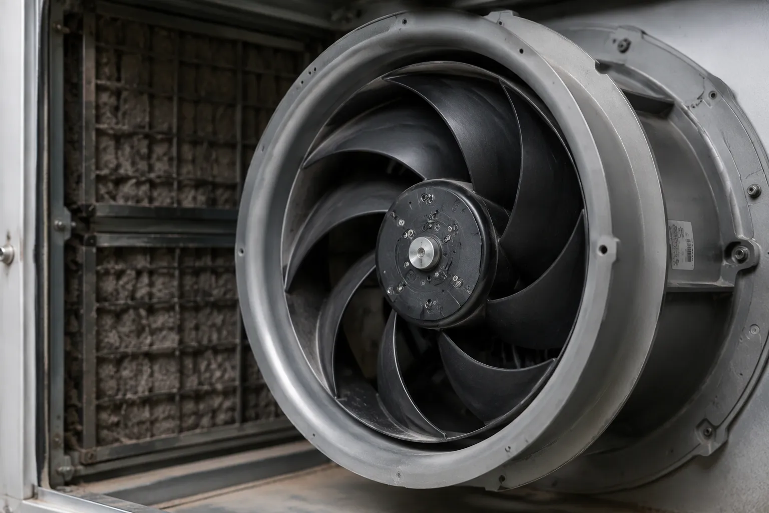
The shape of the impeller decides how much pressure an axial fan can build before airflow drops off. A flat, stamped blade works well in free air. It loses that edge once a dense dust filter loads the cabinet. Impellers shaped for good airflow change the result. An airfoil cross-section guides air smoothly along the blade surface and delays separation at higher pressure. That delay pushes the fan curve upward across the working range.
Blade count, chord, and twist angle each play a part. More blades and a wider chord add surface area for pressure generation. A progressive twist angle matches the blade's angle of attack to the local air speed from hub to tip. The result is a pressure-flow curve that stays flatter near the filter's operating resistance. A cement plant cabinet with a loaded pad then keeps more cfm than a plain-blade fan would deliver. CNC machine builders see the same benefit in tight enclosures with fine mesh guards.
Tip Clearance and Flow Sealing
Air escapes through the gap between blade tip and housing. That leakage costs pressure, and the loss grows as static pressure rises. Tight tip clearance limits the escape path. A guide ring or venturi inlet smooths the entry and cuts turbulence at the blade edge. A diffuser downstream turns leftover speed into recovered pressure. Together these features protect delivered airflow under system resistance.
Belmont uses this thinking across its axial fan range. CFD-optimized airfoil blades, built-in diffusers, and guide rings appear in its EC and AC designs. The 400mm Low Noise AC Axial Fan brings these static pressure capabilities into cabinet cooling. Its plastic impeller and die-cast aluminum rotor hold shape under steady load. Real airflow then tracks the design estimate through the filter's service life.
Higher rotational speed and lower rotating mass help an axial fan answer moderate resistance with quick airflow recovery. Very high resistance changes the picture. A compact forward-curved centrifugal or radial plug fan then fits better, because its geometry builds pressure more efficiently at low flow. Belmont supplies both families, so the fan curve behavior matches the duty. A dust-removal control cabinet with a coarse pre-filter suits the axial fan. A sealed enclosure with a deep, dense filter bank may suit the centrifugal option. Matching blade design to the filter's resistance keeps airflow where the cabinet needs it.
System Design and Fan Selection
Filter Maintenance and Airflow Recovery
Good cabinet design makes the fan's job easier. Filter staging puts a coarse pre-filter in front of a finer pad, so the dense layer gets less dust. Deeper pleats add more surface area and spread the pressure drop across more media. A regular cleaning and replacement schedule stops resistance from rising past the design point. Duct layout matters too. Short, straight runs with few bends lower added system resistance before air even reaches the cabinet.
These steps protect real airflow over time. A filter clogs slowly, and each gram of dust raises the pressure the fan must push against. Maintenance crews who log pressure drop can swap media before airflow drops off. That habit keeps installed airflow close to the design estimate.
When to Choose a Centrifugal Fan
Fan selection should start at the real operating point, not the catalog number. Designers match the fan curve to the filter's clean and dirty resistance limits. They then read actual delivered airflow at that crossing. An EC motor option adds speed control, so the fan can adjust as resistance rises and save energy at part load.
Belmont supports this process with axial fan sizes from 200 mm to 910 mm and airflow up to 32,000 m³/h. AC and EC options, OEM/ODM customization, and a 7–15 day standard lead time suit moderate-to-high resistance cabinet cooling. For dusty plants, a high static pressure ac axial fan with airfoil blades is the preferred choice. It holds real airflow delivered through dense pads.
Very high resistance changes the answer. Compact forward-curved centrifugal and radial plug fans then fit best, because their shape builds pressure at low flow. Both families are valid for different conditions. A Spanish HVAC manufacturer proved the axial route: EC axial fans cut energy use by 18% and noise by 5.7 dB(A). Belmont's selection team helps CNC, cement, mining, and dust-removal cabinet builders match fan curve behavior to their real installed airflow.
Three forces work together under a dense dust filter. Torque reserve keeps an axial fan spinning near its design speed. Pressure-oriented blades lift the fan curve, so static pressure builds without choking flow. Smart layout and scheduled filter changes hold resistance down. Together they protect real airflow in dusty plant cabinets.
Buyers should size on real operating conditions, not catalog numbers. Check delivered airflow at the filter's dirty limit, and clean or swap pads on schedule. A compact centrifugal fan fits only when resistance is more than an axial fan can handle. Match fan technology to the application, and delivered airflow follows.
FAQ
Why does a standard axial fan lose so much airflow behind a dense dust filter?
A dense pad adds resistance, and that resistance goes up as airflow increases. The fan curve and the system curve meet at a higher pressure and a lower flow. A fan with weak torque reserve also slows down, so delivered airflow drops more than the filter alone would cause.
What keeps an AC axial fan near its design speed as resistance rises?
Torque reserve does the work. A motor with enough margin keeps slip small, so the impeller stays close to design speed and the fan curve keeps its shape. Class F insulation and maintenance-free ball bearings then support steady duty through long filter service intervals.
Which Belmont axial fan suits a dusty control cabinet?
The 400mm Low Noise AC Axial Fan fits many cabinet duties. It runs on 380/400V at 50/60 Hz, delivers 3850/4400 m³/h, and holds noise to 60/63 dB(A). Class F insulation and IP54 protection suit steady, restricted operation. Belmont sizes units from 200 mm to 910 mm, up to 32,000 m³/h.
When should a dusty plant choose a centrifugal fan instead?
Very high resistance favors a compact forward-curved centrifugal or radial plug fan, because that shape builds pressure at low flow. Moderate-to-high resistance still suits a high static pressure axial fan with airfoil blades. Belmont supplies both families, so the choice follows the real operating point.
How can a plant keep cabinet airflow stable between filter changes?
Put a coarse pre-filter ahead of the fine pad, use deeper pleats, and keep duct runs short and straight. Log pressure drop and swap media before airflow falls off. These steps hold system resistance near the design point, so the fan keeps delivering its rated airflow.


